This project is electronic blood pressure monitor research platform with Oscillometric method, include SBP and DBP estimate algorithm, Atrial Fibrillation detection algorithm, calibration curve, GUI tool for fine-tune BP algorithm...etc, ofcourse, this is research use only.
Search
2019年11月9日 星期六
2019年9月29日 星期日
Enable STM32F4 FPU
1. ./Libraries/CMSIS/Device/ST/STM32F4xx/Include/stm32f4.h -> add
#include <arm_math.h>
2. ./system_stm32f4xx.c -> in "void SystemInit(void)" add
#if (__FPU_PRESENT == 1) && (__FPU_USED == 1)
SCB->CPACR |= ((3UL <<10*2)|(3UL <<11*2));/* set CP10 and CP11 Full Access */
#endif
3.main.c add
#define __FPU_PRESENT
#define __FPU_USED
#include <arm_math.h>
2. ./system_stm32f4xx.c -> in "void SystemInit(void)" add
#if (__FPU_PRESENT == 1) && (__FPU_USED == 1)
SCB->CPACR |= ((3UL <<10*2)|(3UL <<11*2));/* set CP10 and CP11 Full Access */
#endif
3.main.c add
#define __FPU_PRESENT
#define __FPU_USED
wxECGAnalyzer - cross platform ECG signal process tool
Detection of abnormal rhythm morphologies is more difficult than normal beat, therefore, we need to collect abnormal rhythm signals in clinical practice to improve the detection of QRS-complex.
This project is for Electrocardiogram(ECG) signal algorithms design and validation, include preprocessing, QRS-Complex detection, embedded system validation, ECG segmentation, label your machine learning dataset, and clinical trial...etc.
For algorithm performance, in ANSI/AAMI EC38,it is required that the detected QRS shall in the 150ms range of the signed point from annotation by human exper.
目前僅用MIT-BIH等標準心律不整資料庫或是生理訊號挑戰賽提供的標註資料,理論上很難得到超越其標注的學習模型,實務上還是需要配合其他臨床實驗搜集更多案例強化模型,下個To-Do會用標準資料庫訓練分類模型增加基本的自動化標註,目前僅針對臨床實時運行的特殊案例配合人工選擇QRS-Complex演算法自動切片。
This project is for Electrocardiogram(ECG) signal algorithms design and validation, include preprocessing, QRS-Complex detection, embedded system validation, ECG segmentation, label your machine learning dataset, and clinical trial...etc.
For algorithm performance, in ANSI/AAMI EC38,it is required that the detected QRS shall in the 150ms range of the signed point from annotation by human exper.
目前僅用MIT-BIH等標準心律不整資料庫或是生理訊號挑戰賽提供的標註資料,理論上很難得到超越其標注的學習模型,實務上還是需要配合其他臨床實驗搜集更多案例強化模型,下個To-Do會用標準資料庫訓練分類模型增加基本的自動化標註,目前僅針對臨床實時運行的特殊案例配合人工選擇QRS-Complex演算法自動切片。
2019年7月21日 星期日
Cross-Platform Serial Port Library
This is cross-platform(build passing High-Sierra and Win10) serial port library written in C++ , and for demo application wxTerm.
SerialPortLibrary in more detail : Github
2019年1月13日 星期日
STM32F4 PCA9685 Driver For Servo Motor
In this case, period 0.5ms~2.5ms, and maximum angle 180 ,if SetPWNFreq = 50Hz, 1000ms/50 = 20ms
2018年12月20日 星期四
Pulse Oximeter with MAX3010X
在同一波長下針對Hb和HbO2的吸收(extinction coefficient or absorption coefficient)有差異,而如果要求SPo2量測兩個不同波長的吸收就可以求解一個未知數。
因為光對於動脈微血管血液的變化(隨著心率)會有交流訊號,而其他的組織(吸收散射反射)則是直流成分,因此將兩波長反射量變化正規化後的結果作為R-Ration(SPo2為非線性),利用經驗公式A, B係數可得一SPo2曲線,例如660nm/940nm = 1, SPo2 = 85%,例如A - B = 110 - 25 斜率。
具體實現只要動態的將直流成分除去,並且將兩波長光直流水平控制在一範圍(SPo2都有類似PGA的功能),得到的兩波長交流訊號RMS比值即可推算SPo2。
以下Github包含STM32F4 Driver for MAX30100(移植Reference 1.範例),和MAC OS X上的C++ wxWidgets GUI(左下角顯示SPo2)可透過VCP與STM32F4通訊,當然除了此方法使用更多的波長可以使SPo2求解聯立方程更加準確,並且實務上會做更高精度的SPo2曲線的建立以及motion artifact除去等。
因為光對於動脈微血管血液的變化(隨著心率)會有交流訊號,而其他的組織(吸收散射反射)則是直流成分,因此將兩波長反射量變化正規化後的結果作為R-Ration(SPo2為非線性),利用經驗公式A, B係數可得一SPo2曲線,例如660nm/940nm = 1, SPo2 = 85%,例如A - B = 110 - 25 斜率。
具體實現只要動態的將直流成分除去,並且將兩波長光直流水平控制在一範圍(SPo2都有類似PGA的功能),得到的兩波長交流訊號RMS比值即可推算SPo2。
Download :
Demo :
Reference :
1. https://morf.lv/implementing-pulse-oximeter-using-max30100
2. http://www.ti.com/lit/an/slaa274b/slaa274b.pdf
3. http://www.ti.com/lit/ug/tidu542/tidu542.pdf
4. http://sam-koblenski.blogspot.com/2015/11/everyday-dsp-for-programmers-dc-and.html
2018年10月4日 星期四
Continuous Non Invasive Blood Pressure Research Platform (ECG and PPG) Pulse Arrival Time Based
This project is cuffless cNIBP research platform with ECG(two-electrode) and PPG
In cuffless non-invasive blood pressure monitor field, we with the accurate calibration of PAT to BP, beat-to-beat BP can be estimated from PAT. On the basis of the theoretical relationship between PAT and BP and their experimental or empirical relationship, various models that correlate PAT with BP have been established.
PAT and BP with Regression:
In cuffless non-invasive blood pressure monitor field, we with the accurate calibration of PAT to BP, beat-to-beat BP can be estimated from PAT. On the basis of the theoretical relationship between PAT and BP and their experimental or empirical relationship, various models that correlate PAT with BP have been established.
PAT and BP with Regression:
Pulse transit time (PTT) is the time it takes for the pressure or flow wave to propagate between two arterial sites. PTT measured as the time delay between invasive proximal and distal blood pressure or flow, and PTT(propagate time) can be converted to Pulse Wave Velocity(PWV is speed unit).
the most used is the R-wave(QRS Complex) in the electrocardiogram (ECG) and combine pulsemeter(piezo or PPG), leading to the so called pulse arrival time (PAT). PAT is not exactly the PTT, as it includes the time interval between ventricular depolarization and the opening of the aortic valve which is known as pre-ejection period (PEP) and it varies beat-to-beat.
Most efforts have employed the time delay between ECG and finger photoplethysmography (PPG) waveforms as a convenient surrogate of PTT.
However, these conventional pulse arrival time (PAT) measurements include the pre-ejection period (PEP) and the time delay through small, muscular arteries and may thus be an unreliable marker of BP.
Shortcoming is that PAT includes the pre-ejection period (PEP) in addition to PTT. Since the PEP component depends on the electromechanical functioning of the heart, it can change independently of PTT and thus BP.
Because the ECG QRS-Complex is not the starting point for blood to actually enter the radial artery, it is a biopotential to depolarization of the sinus node
This project only for research
Reference :
[1] Continuous Blood Pressure Measurement from Invasive to Unobtrusive: Celebration of 200th Birth Anniversary of Carl Ludwig
[2] Cuff-Less and Continuous Blood Pressure Monitoring: A Methodological Review
2018年9月7日 星期五
STM32F407-MG996R and MAC OS X GUI tester
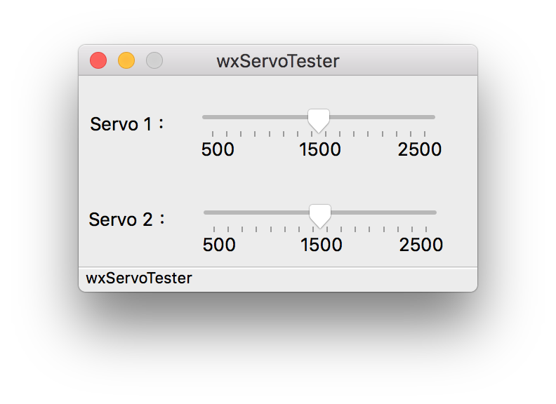
STM32F407 with PWM to control MG996R, and GUI tester for MAX OS X
1.
make STM32F407 project, and burn to board.(0.5ms~2.5ms)
2.
build GUI
g++ -o2 -o wxservotester.app wxservotester.cpp serialport.cpp connectargsdlg.cpp `wx-config --cxxflags --libs`
3.
wxservotester.app -> Tools -> ConnectDevice
4.
Test your servo motor!
1.
make STM32F407 project, and burn to board.(0.5ms~2.5ms)
2.
build GUI
g++ -o2 -o wxservotester.app wxservotester.cpp serialport.cpp connectargsdlg.cpp `wx-config --cxxflags --libs`
3.
wxservotester.app -> Tools -> ConnectDevice
4.
Test your servo motor!
2018年7月8日 星期日
Real-Time wxSignalProcess with Serial Port(VCP) for MAC OS X
一個C++ MAC OS X的範例從/dev/tty.* or /dev/cu.* device driver取得Virtual COM Port的資料並且顯示在GUI,Framework用wxWidgets 3.0以及MRPT修改版的wxMathPlot 0.1.2,和修改以前Linux POSIX API的Class組合,多增加ioctl讀取,以及一個STM32F4的DMA+ADC的Example可供測試。
過去同性質不同平台的軟體參考:
2018年4月16日 星期一
2015年6月4日 星期四
HDC1000 Breakout
HDC1000轉接版實驗用,STM32 PB15連接HDC1000 DRDYn開外部中斷等接收資料即可,轉換公式看Datasheet,下面是STM32 Example,話說STM32的Hardware IIC真的很鳥...
example:
壹圓下面那個
example:
#include "stm32f10x.h"
#include "stdio.h"
#define HDC1000_ADDR 0x40 << 1
#define HDC1000_BOTH_TEMP_HUMI 0x10
#define HDC1000_TEMP_HUMI_14BIT 0x00
#define HDC1000_HEAT_ON 0x20
#define HDC1000_TEMP 0X00
#define HDC1000_HUMI 0X01
#define HDC1000_CONFIG 0x02
#define true 1
#define false 0
uint8_t HDC1000_SYNC = true;
uint8_t HDC1000_FLAG = HDC1000_TEMP;
double temperature = 0,humidity = 0;
volatile uint32_t delay = 0;
void Delay(volatile uint32_t n)
{
delay = n;
while(delay != 0);
}
void Init_I2C() {
I2C_InitTypeDef I2C_InitStructure;
GPIO_InitTypeDef GPIO_InitStructure;
I2C_Cmd(I2C1,ENABLE);
RCC_APB1PeriphClockCmd(RCC_APB1Periph_I2C1, ENABLE);
RCC_APB2PeriphClockCmd(RCC_APB2Periph_GPIOB, ENABLE);
GPIO_InitStructure.GPIO_Pin = GPIO_Pin_6 | GPIO_Pin_7;
GPIO_InitStructure.GPIO_Speed = GPIO_Speed_50MHz;
GPIO_InitStructure.GPIO_Mode = GPIO_Mode_AF_OD;
GPIO_Init(GPIOB, &GPIO_InitStructure);
I2C_InitStructure.I2C_Mode = I2C_Mode_SMBusHost;
I2C_InitStructure.I2C_DutyCycle = I2C_DutyCycle_2;
I2C_InitStructure.I2C_OwnAddress1 = 0x00;
I2C_InitStructure.I2C_Ack = I2C_Ack_Enable;
I2C_InitStructure.I2C_AcknowledgedAddress = I2C_AcknowledgedAddress_7bit;
I2C_InitStructure.I2C_ClockSpeed = 100000 ;
I2C_Init(I2C1, &I2C_InitStructure);
}
void I2C_start(I2C_TypeDef* I2Cx, uint8_t address, uint8_t direction){
while(I2C_GetFlagStatus(I2Cx, I2C_FLAG_BUSY));
I2C_GenerateSTART(I2Cx, ENABLE);
while(!I2C_CheckEvent(I2Cx, I2C_EVENT_MASTER_MODE_SELECT));
I2C_Send7bitAddress(I2Cx, address, direction);
if(direction == I2C_Direction_Transmitter){
while(!I2C_CheckEvent(I2Cx, I2C_EVENT_MASTER_TRANSMITTER_MODE_SELECTED));
} else if(direction == I2C_Direction_Receiver){
while(!I2C_CheckEvent(I2Cx, I2C_EVENT_MASTER_RECEIVER_MODE_SELECTED));
}
}
void I2C_write(I2C_TypeDef* I2Cx, uint8_t data)
{
I2C_SendData(I2Cx, data);
while(!I2C_CheckEvent(I2Cx, I2C_EVENT_MASTER_BYTE_TRANSMITTED));
}
uint8_t I2C_read_ack(I2C_TypeDef* I2Cx){
uint8_t data;
I2C_AcknowledgeConfig(I2Cx, ENABLE);
while( !I2C_CheckEvent(I2Cx, I2C_EVENT_MASTER_BYTE_RECEIVED) );
data = I2C_ReceiveData(I2Cx);
return data;
}
uint8_t I2C_read_nack(I2C_TypeDef* I2Cx){
uint8_t data;
I2C_AcknowledgeConfig(I2Cx, DISABLE);
I2C_GenerateSTOP(I2Cx, ENABLE);
while( !I2C_CheckEvent(I2Cx, I2C_EVENT_MASTER_BYTE_RECEIVED) );
data = I2C_ReceiveData(I2Cx);
return data;
}
void I2C_stop(I2C_TypeDef* I2Cx){
I2C_GenerateSTOP(I2Cx, ENABLE);
}
void Init_BT(void){
GPIO_InitTypeDef GPIO_InitStructure;
USART_InitTypeDef USART_InitStructure;
NVIC_InitTypeDef interrup;
RCC_APB2PeriphClockCmd(RCC_APB2Periph_GPIOA, ENABLE);
RCC_APB1PeriphClockCmd(RCC_APB1Periph_USART2, ENABLE);
GPIO_InitStructure.GPIO_Pin = GPIO_Pin_2;
GPIO_InitStructure.GPIO_Speed = GPIO_Speed_50MHz;
GPIO_InitStructure.GPIO_Mode = GPIO_Mode_AF_PP;
GPIO_Init(GPIOA, &GPIO_InitStructure);
GPIO_InitStructure.GPIO_Pin = GPIO_Pin_3;
GPIO_InitStructure.GPIO_Mode = GPIO_Mode_IN_FLOATING;
GPIO_Init(GPIOA, &GPIO_InitStructure);
USART_InitStructure.USART_BaudRate = 9600;
USART_InitStructure.USART_WordLength = USART_WordLength_8b;
USART_InitStructure.USART_StopBits = USART_StopBits_1;
USART_InitStructure.USART_Parity = USART_Parity_No;
USART_InitStructure.USART_HardwareFlowControl = USART_HardwareFlowControl_None;
USART_InitStructure.USART_Mode = USART_Mode_Rx | USART_Mode_Tx;
USART_Init(USART2, &USART_InitStructure);
USART_Cmd(USART2, ENABLE);
}
void BT_Send_String(volatile char *string)
{
while(*string){
USART_SendData(USART2,*string);
++string;
while(USART_GetFlagStatus(USART2,USART_FLAG_TC) == RESET){}
}
}
void HDC1000Start()
{
uint8_t config = HDC1000_BOTH_TEMP_HUMI | HDC1000_TEMP_HUMI_14BIT | HDC1000_HEAT_ON;
I2C_start(I2C1, HDC1000_ADDR, I2C_Direction_Transmitter);
I2C_write(I2C1, HDC1000_CONFIG);
I2C_write(I2C1, config);
I2C_write(I2C1, 0x00);
I2C_stop(I2C1);
Delay(20);
}
void HDC1000DataRequest(uint8_t reg)
{
if((HDC1000_FLAG == reg) && HDC1000_SYNC){
HDC1000_SYNC = false;
I2C_start(I2C1, HDC1000_ADDR, I2C_Direction_Transmitter);
I2C_write(I2C1, reg);
I2C_stop(I2C1);
}
else if((HDC1000_FLAG == reg) && HDC1000_SYNC){
HDC1000_SYNC = false;
I2C_start(I2C1, HDC1000_ADDR, I2C_Direction_Transmitter);
I2C_write(I2C1, reg);
I2C_stop(I2C1);
}
}
double HDC1000GetTemp()
{
double temp = 0;
I2C_start(I2C1, HDC1000_ADDR, I2C_Direction_Receiver);
temp = I2C_read_ack(I2C1) << 8;
temp += I2C_read_nack(I2C1);
return temp / 65536.0 * 165.0 - 40.0;
}
double HDC1000GetHumi()
{
double humi = 0;
I2C_start(I2C1, HDC1000_ADDR, I2C_Direction_Receiver);
humi = I2C_read_ack(I2C1) << 8;
humi += I2C_read_nack(I2C1);
return humi / 65536.0 * 100.0;
}
void HDC1000EXTI15()
{
GPIO_InitTypeDef GPIO_InitStructure;
NVIC_InitTypeDef NVIC_InitStructure;
EXTI_InitTypeDef EXTI_InitStructure;
RCC_APB2PeriphClockCmd(RCC_APB2Periph_GPIOB | RCC_APB2Periph_AFIO, ENABLE);
GPIO_InitStructure.GPIO_Pin = GPIO_Pin_15;
GPIO_InitStructure.GPIO_Mode = GPIO_Mode_IN_FLOATING;
GPIO_InitStructure.GPIO_Speed = GPIO_Speed_10MHz;
GPIO_Init(GPIOB, &GPIO_InitStructure);
GPIO_EXTILineConfig(GPIO_PortSourceGPIOB, GPIO_PinSource15);
EXTI_InitStructure.EXTI_Line = EXTI_Line15;
EXTI_InitStructure.EXTI_Mode = EXTI_Mode_Interrupt;
EXTI_InitStructure.EXTI_Trigger = EXTI_Trigger_Falling;
EXTI_InitStructure.EXTI_LineCmd = ENABLE;
EXTI_Init(&EXTI_InitStructure);
NVIC_InitStructure.NVIC_IRQChannel = EXTI15_10_IRQn;
NVIC_InitStructure.NVIC_IRQChannelPreemptionPriority = 0;
NVIC_InitStructure.NVIC_IRQChannelSubPriority = 0;
NVIC_InitStructure.NVIC_IRQChannelCmd = ENABLE;
NVIC_Init(&NVIC_InitStructure);
}
int main(){
Init_I2C();
Init_BT();
SystemInit();
if(SysTick_Config(SystemCoreClock / 1000)){
while(1);
}
HDC1000Start();
HDC1000EXTI15();
while(true){
if(HDC1000_FLAG == HDC1000_TEMP){
HDC1000DataRequest(HDC1000_TEMP);
}
else if(HDC1000_FLAG == HDC1000_HUMI){
HDC1000DataRequest(HDC1000_HUMI);
}
}
}
void SysTick_Handler(void)
{
if(delay != 0){
delay--;
}
}
void EXTI15_10_IRQHandler(void) {
if(EXTI_GetITStatus(EXTI_Line15) != RESET) {
if(HDC1000_FLAG == HDC1000_TEMP){
HDC1000_FLAG = HDC1000_HUMI;
temperature = HDC1000GetTemp();
}
else if(HDC1000_FLAG == HDC1000_HUMI){
HDC1000_FLAG = HDC1000_TEMP;
humidity = HDC1000GetHumi();
}
char str[256];
sprintf(str, "temperature:%.2f humidity:%.2f%%\n",temperature,humidity);
BT_Send_String(str);
HDC1000_SYNC = true;
}
EXTI_ClearITPendingBit(EXTI_Line15);
}
Download:
2015年1月18日 星期日
STM32F10X Nano ver1.0.0
2014年12月28日 星期日
JLINK ARM-OB STM32F103C8T6 (DIP)
說來也蠢,之前就想做STM32的debugger,我慣用的是STLINK + ST-UTIL + ARM-GDB,所以習慣上我還是比較常用discovery上的STLINK/V2,前陣子在網路看到一個叫JLINK的東西以為也可以用ST-Tools,結果直到昨天做了才知道這只能用SEGGER-Tools XDDDDD,還好本來SMD版本要送去淘寶給人洗板不過做了DIP版就發現XD,但是其實也還不錯用拉只是我不習慣而已,將firmware由SWD寫進後用JLINK-Commander可以將firmware升級,要注意的是輸出入的電壓都是3.3v!
Download:
2014年5月18日 星期日
STM32F10X Nano v0.0.1
最近比較有空上來更新一下blog,前陣子都在弄STM32的東西,所以為了方便畫了一個可以直接插上麵包板的實驗板,能相容STM32F100C8T6的IC應該都可以直接用,我用STM32F103C8T6也可以,當然load file不同而已,附上一個example測試PA0 weak up與PC13 led,我自己在使用都是用USART1去Upload程式,這個唯一的優點大概就是電路板可以用單面感光PCB做出來比較簡單,未來有時間會弄個jlink換SWD,然後再寫個GUI版的USART & SWD Upload程式。
Part List:
JP3中間那支腳是B00T0,可與上下HIGH & LOW短路,JP1從最右邊數過來分別是5V、3.3V、GND,JP1最左邊是PA0一直到PB11,JP2最右邊開始則是PB12到PB9,都只有GPIO,PC13預留實驗用LED,PC14、15也預留可以焊音叉式Crystal。
Eaxmple:
Part List:
- IC1:STM32F10X
- U1:AMS-1117 3.3V
- U2:8MHz Crystall
- C1~C7:0.1uF
- C8~C9:22pF
- R1:1k ohm
- R2~R3:10k ohm
- L1~L2:電源與PC13 LED
- B1~B2:Reset與PA0 weak up
- JP1~JP3:GPIO與BOOT選擇
JP3中間那支腳是B00T0,可與上下HIGH & LOW短路,JP1從最右邊數過來分別是5V、3.3V、GND,JP1最左邊是PA0一直到PB11,JP2最右邊開始則是PB12到PB9,都只有GPIO,PC13預留實驗用LED,PC14、15也預留可以焊音叉式Crystal。
Eaxmple:
#include "stm32f10x.h"
#include "stdio.h"
volatile uint32_t delay = 0;
void USART1_Send_Sting(char *string){
while(*string){
USART_SendData(USART1, (unsigned short int) *string++);
while (USART_GetFlagStatus(USART1, USART_FLAG_TC) == RESET);
}
}
void Init_WU()
{
GPIO_InitTypeDef GPIO_InitStruct;
RCC_APB2PeriphClockCmd(RCC_APB2Periph_GPIOA,ENABLE);
GPIO_InitStruct.GPIO_Pin = GPIO_Pin_0;
GPIO_InitStruct.GPIO_Mode = GPIO_Mode_IN_FLOATING;
GPIO_Init(GPIOA, &GPIO_InitStruct);
}
void Init_UART(){
GPIO_InitTypeDef GPIO_InitStructure;
USART_InitTypeDef USART_InitStructure;
NVIC_InitTypeDef interrup;
RCC_APB2PeriphClockCmd(RCC_APB2Periph_GPIOA|RCC_APB2Periph_USART1, ENABLE);
GPIO_InitStructure.GPIO_Pin = GPIO_Pin_9;
GPIO_InitStructure.GPIO_Speed = GPIO_Speed_50MHz;
GPIO_InitStructure.GPIO_Mode = GPIO_Mode_AF_PP;
GPIO_Init(GPIOA, &GPIO_InitStructure);
GPIO_InitStructure.GPIO_Pin = GPIO_Pin_10;
GPIO_InitStructure.GPIO_Mode = GPIO_Mode_IN_FLOATING;
GPIO_Init(GPIOA, &GPIO_InitStructure);
USART_InitStructure.USART_BaudRate = 9600;
USART_InitStructure.USART_WordLength = USART_WordLength_8b;
USART_InitStructure.USART_StopBits = USART_StopBits_1;
USART_InitStructure.USART_Parity = USART_Parity_No;
USART_InitStructure.USART_HardwareFlowControl = USART_HardwareFlowControl_None;
USART_InitStructure.USART_Mode = USART_Mode_Rx | USART_Mode_Tx;
USART_Init(USART1, &USART_InitStructure);
USART_Cmd(USART1, ENABLE);
USART_ITConfig(USART1,USART_IT_RXNE,ENABLE);
interrup.NVIC_IRQChannel = USART1_IRQn;
interrup.NVIC_IRQChannelPreemptionPriority = 0;
interrup.NVIC_IRQChannelSubPriority = 0;
interrup.NVIC_IRQChannelCmd = ENABLE;
NVIC_Init(&interrup);
NVIC_EnableIRQ(USART1_IRQn);
}
void Init_BT(void){
GPIO_InitTypeDef GPIO_InitStructure;
USART_InitTypeDef USART_InitStructure;
NVIC_InitTypeDef interrup;
RCC_APB1PeriphClockCmd(RCC_APB2Periph_GPIOA|RCC_APB1Periph_USART2, ENABLE);
GPIO_InitStructure.GPIO_Pin = GPIO_Pin_2;
GPIO_InitStructure.GPIO_Speed = GPIO_Speed_50MHz;
GPIO_InitStructure.GPIO_Mode = GPIO_Mode_AF_PP;
GPIO_Init(GPIOA, &GPIO_InitStructure);
GPIO_InitStructure.GPIO_Pin = GPIO_Pin_3;
GPIO_InitStructure.GPIO_Mode = GPIO_Mode_IN_FLOATING;
GPIO_Init(GPIOA, &GPIO_InitStructure);
USART_InitStructure.USART_BaudRate = 9600;
USART_InitStructure.USART_WordLength = USART_WordLength_8b;
USART_InitStructure.USART_StopBits = USART_StopBits_1;
USART_InitStructure.USART_Parity = USART_Parity_No;
USART_InitStructure.USART_HardwareFlowControl = USART_HardwareFlowControl_None;
USART_InitStructure.USART_Mode = USART_Mode_Rx | USART_Mode_Tx;
USART_Init(USART2, &USART_InitStructure);
USART_Cmd(USART2, ENABLE);
USART_ITConfig(USART2,USART_IT_RXNE,ENABLE);
interrup.NVIC_IRQChannel = USART2_IRQn;
interrup.NVIC_IRQChannelPreemptionPriority = 0;
interrup.NVIC_IRQChannelSubPriority = 0;
interrup.NVIC_IRQChannelCmd = ENABLE;
NVIC_Init(&interrup);
NVIC_EnableIRQ(USART2_IRQn);
}
void BT_Send_String(volatile char *string)
{
while(*string){
USART_SendData(USART2,*string);
++string;
while(USART_GetFlagStatus(USART2,USART_FLAG_TC) == RESET){}
}
}
void PWR_StandbyMode( void )
{
RCC_APB1PeriphClockCmd(RCC_APB1Periph_PWR | RCC_APB1Periph_BKP, ENABLE);
PWR_WakeUpPinCmd(ENABLE);
PWR_BackupAccessCmd(ENABLE);
PWR_ClearFlag(PWR_FLAG_SB);
PWR_EnterSTANDBYMode();
}
void Init_Default_Led(void)
{
GPIO_InitTypeDef led;
RCC_APB2PeriphClockCmd(RCC_APB2Periph_GPIOC,ENABLE);
led.GPIO_Pin = GPIO_Pin_13;
led.GPIO_Mode = GPIO_Mode_Out_PP;
led.GPIO_Speed = GPIO_Speed_50MHz;
GPIO_Init(GPIOC,&led);
}
void Delay(volatile uint32_t n)
{
delay = n;
while(delay != 0);
}
int main(){
Init_UART();
Init_BT();
Init_Default_Led();
Init_WU();
SystemInit();
if(SysTick_Config(SystemCoreClock / 1000)){
while(1);
}
char str[256];
sprintf(str,"\n\nFlash Size : %dKb\nUID : %X%X%X\n",*(volatile u16*)(0x1FFFF7E0),
*(volatile u32*)(0x1FFFF7E8),*(volatile u32*)(0x1FFFF7EC),*(volatile u32*)(0x1FFFF7F0));
USART1_Send_Sting(str);
BT_Send_String(str);
while(1){
GPIO_SetBits(GPIOC,GPIO_Pin_13);
Delay(1000);
GPIO_ResetBits(GPIOC,GPIO_Pin_13);
PWR_StandbyMode();
}
}
void USART1_IRQHandler(void)
{
if(USART_GetITStatus(USART1,USART_IT_RXNE) != RESET){
char c = USART1->DR/*USART_ReciveData(USART1)*/;
USART_SendData(USART1,c);
}
}
void USART2_IRQHandler(void)
{
if(USART_GetITStatus(USART2,USART_IT_RXNE) != RESET){
char c = USART2->DR/*USART_ReciveData(USART2)*/;
USART_SendData(USART2,c);
}
}
void SysTick_Handler(void)
{
if(delay != 0){
delay--;
}
}
2014年3月29日 星期六
STM32 Remap & Linker Script
STM32有幾個I/O啟動預設是JTAG & SWD,如果要當一般的GPIO用要通過Remap的方式映射功能,最重要的是要先啟動RCC再Remap順序反過來當然會失敗。
幾個我常用的STM32 Chip的Linker Script,Startup File Library找跟Chip同系列的link就可以了。
最近又開始研究STM32F1系列,測試了大多數功能後最近有時間可以layout幾片類似Arduino Nano的板子來用,還有弄ARM-OB才可以用SWD。
RCC_APB2PeriphClockCmd(RCC_APB2Periph_GPIOB,ENABLE);
RCC_APB2PeriphClockCmd(RCC_APB2Periph_AFIO, ENABLE);
GPIO_PinRemapConfig(GPIO_Remap_SWJ_JTAGDisable, ENABLE);
幾個我常用的STM32 Chip的Linker Script,Startup File Library找跟Chip同系列的link就可以了。
最近又開始研究STM32F1系列,測試了大多數功能後最近有時間可以layout幾片類似Arduino Nano的板子來用,還有弄ARM-OB才可以用SWD。
2013年12月24日 星期二
STM32 Toolchain Build For Mac OS X
1.先裝xcode以及homebrew接著在terminal執行
brew install mpfr gmp libmpc texinfo libusb-compat libftdi wget automake libtool
3-1.改.bashrc後source .bashrc
4.將STM32F4DISCOVERY與PC連接
5.執行st-util
6.執行arm-none-eabi-gdb並且連接
7.下載examples
stm32f4-examples
or
STM32F4-workarea
8.隨便選一個project make
9.load elf
10.run
4.將STM32F4DISCOVERY與PC連接
5.執行st-util
6.執行arm-none-eabi-gdb並且連接
tar ext localhost:42427.下載examples
stm32f4-examples
or
STM32F4-workarea
8.隨便選一個project make
9.load elf
load YourPath/spi.elf10.run
2013年4月13日 星期六
STM32F10xC DIY
今天趁有空稍微確認了幾點,首先是電源電路用3.3v並聯三個0.1u陶瓷電容與一個1u無極性電解電容,接著reset電路可以參考這裡,然後8 or 12MHz Crystal配上22p陶瓷電容(PD0 OSC_IN、PD1 OSC_OUT),32.768KHz Crtstal配10p陶瓷電容(PC14-OSC32_IN、PC15-OSC32_OUT),VBAT與所有VDD都接3.3v然後所有VSS都接地,最後將USB to Serial的RX&TX接到STM32F10xC(我在STM32F100C8T6B測試)的PA9&PA10。
接著toolchain因為自己DIY沒有STLINK所以必須用UART的方式去將binary upload到flash,在windows下可以用Keil ARM編譯code接著就可以用MCUISP將binary upload,而linux可以找ARM-Toolchain編譯code然後用stm32flash將binary upload,要注意的是upload前要先將BOOT 0接上3.3v然後最好再按下reset(因為像是MCUISP上一次燒錄完程式會自動reset但stm32flash不會),接著再將BOOT 0 接地並且按下reset按鈕就可以運作了。
話說先畫成轉接板接到breadboard再搭電路對我來說比較保險,而且我不太會焊電子零件這樣小小一個我也要弄30分鐘(看以前學電子的學長不用一下就好了)...下次有空應該可以Layout出完整的版子了:Q
訂閱:
文章 (Atom)


-2.png?raw=true)