2020年4月8日 星期三
MSP430G2 Geiger Counter and True Random Number Generator(TRNG)
清個庫存把MSP430G2433消耗掉做個蓋格計數器跟物理亂數產生器,如果有核種可以找露營燈紗(瓦斯燈芯, 汽化燈燈芯)含釷的可以加快亂數產生,製作時如果電錶調整到1000VDC檔位內阻在10M(查文件)則調整VR1測量蓋格管的電壓為250v實際電壓就大概是400v了,我測試J321βγ和M4011沒問題,但這兩個管子拿強光手電筒照會有Event做輻射測量需要防光,相關資訊都在下面連結。

2019年6月21日 星期五

2018年10月4日 星期四
Continuous Non Invasive Blood Pressure Research Platform (ECG and PPG) Pulse Arrival Time Based
This project is cuffless cNIBP research platform with ECG(two-electrode) and PPG
In cuffless non-invasive blood pressure monitor field, we with the accurate calibration of PAT to BP, beat-to-beat BP can be estimated from PAT. On the basis of the theoretical relationship between PAT and BP and their experimental or empirical relationship, various models that correlate PAT with BP have been established.
PAT and BP with Regression:


-2.png?raw=true)


In cuffless non-invasive blood pressure monitor field, we with the accurate calibration of PAT to BP, beat-to-beat BP can be estimated from PAT. On the basis of the theoretical relationship between PAT and BP and their experimental or empirical relationship, various models that correlate PAT with BP have been established.
PAT and BP with Regression:
Pulse transit time (PTT) is the time it takes for the pressure or flow wave to propagate between two arterial sites. PTT measured as the time delay between invasive proximal and distal blood pressure or flow, and PTT(propagate time) can be converted to Pulse Wave Velocity(PWV is speed unit).
the most used is the R-wave(QRS Complex) in the electrocardiogram (ECG) and combine pulsemeter(piezo or PPG), leading to the so called pulse arrival time (PAT). PAT is not exactly the PTT, as it includes the time interval between ventricular depolarization and the opening of the aortic valve which is known as pre-ejection period (PEP) and it varies beat-to-beat.
Most efforts have employed the time delay between ECG and finger photoplethysmography (PPG) waveforms as a convenient surrogate of PTT.
However, these conventional pulse arrival time (PAT) measurements include the pre-ejection period (PEP) and the time delay through small, muscular arteries and may thus be an unreliable marker of BP.
Shortcoming is that PAT includes the pre-ejection period (PEP) in addition to PTT. Since the PEP component depends on the electromechanical functioning of the heart, it can change independently of PTT and thus BP.
Because the ECG QRS-Complex is not the starting point for blood to actually enter the radial artery, it is a biopotential to depolarization of the sinus node
This project only for research

Reference :
[1] Continuous Blood Pressure Measurement from Invasive to Unobtrusive: Celebration of 200th Birth Anniversary of Carl Ludwig
[2] Cuff-Less and Continuous Blood Pressure Monitoring: A Methodological Review
2017年8月1日 星期二
Nixie Clock
C1,C2 如果不裝18650電池就用1000uF以上的電容,R15可以選擇5k~18k 1/4w以上的電阻。Github上有IN-12B與IN-14不過只是管子不同,IN-14的有加NEO-6M-0-001不過校時還沒寫,因為DS3231一年誤差一分鐘而已。


2016年10月4日 星期二

2016年9月24日 星期六
Firework Controller V2
中的裝置新版本,因為Android -Bluetooth太短所以改用2.4G RF控制,加進去火焰偵測和人體紅外線,code for Energia MSP430G2XX3由於PCB在中秋前一天才到所以code離預設的完成度不高不過也不打算再改了,而且今年也沒有機會放到煙火XD相關資料在以下

2016年8月18日 星期四
LD7032 0.5" OLED test board
LD7032的測試版上面放了ATMega328與MSP430FR5739,OLED要吃一個15v的電壓與Drive IC吃5v兩個電壓,15v升壓可以參考下面電路。基本上與對岸出的demo board一樣,這東西唯一麻煩的是connector不是普通的FPC而且超難焊很容易融化...插拔幾次後金手指就接觸不良了...,


2016年5月18日 星期三
MSP430FR5739 Mini


/* Blink


  The basic Energia example.


  Turns on an LED on for one second, then off for one second, repeatedly.


  Change the LED define to blink other LEDs.


  Hardware Required:

  * LaunchPad with an LED


  This example code is in the public domain.

*/


// most launchpads have a red LED

#define LED 30


// the setup routine runs once when you press reset:

void setup() {

  // initialize the digital pin as an output.

  pinMode(LED, OUTPUT);

}


// the loop routine runs over and over again forever:

void loop() {

  digitalWrite(LED, HIGH);   // turn the LED on (HIGH is the voltage level)

  delay(50);               // wait for a second

  digitalWrite(LED, LOW);    // turn the LED off by making the voltage LOW

  delay(50);               // wait for a second

}
2016年5月17日 星期二



2016年4月24日 星期日


2016年2月2日 星期二
CP2102-USB-RS232
焊接QFN零件最好先上一層錫,接著用吸錫線把PAD吸平,然後零件擺好用風槍吹,重點是吹的時候每五秒左右拉高一兩秒然後反覆幾次直到零件焊上,最後再用烙鐵從四邊刷過去補錫即可,每個階段的步驟最好都把助焊劑去除,如果可以USB四線可以都串0R電阻。

2015年12月18日 星期五
MQ Gas Sensors Breakout Board
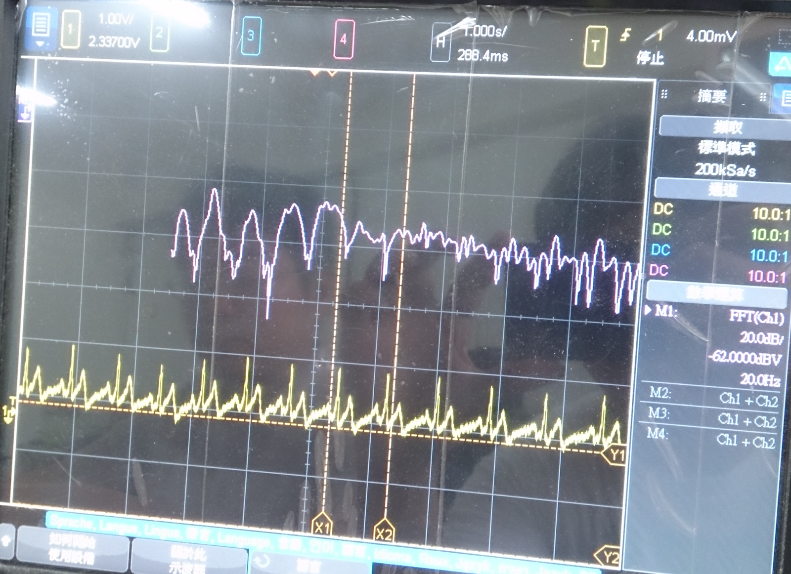
MQ系列轉板,搭配一顆SMD 104P電容和10k VR,下面第一張圖是MQ-2,第二張圖是MQ-3,把MQ系列接反或者電壓接反都能Work只影響偵測到目標氣體時電壓曲線上升或下降,板子Pin中間那根就是AnalogOUT。


示波器為酒精棉片靠近時的反應

Download:
2015年9月21日 星期一
中秋節放煙火 XD
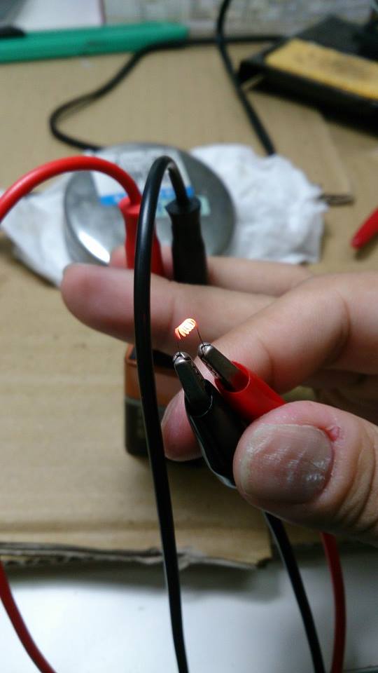
去年中秋節做的東西,用的是Kanthal 鎳鉻合金線,加熱速度要看Datasheet的長度電阻和電流量,短短的不到0.5sec通9v就能加熱到發紅點燃煙火引線了XD,記得把加熱合金線的電源和MCU分開XD



data :
2015年6月4日 星期四
HDC1000 Breakout
HDC1000轉接版實驗用,STM32 PB15連接HDC1000 DRDYn開外部中斷等接收資料即可,轉換公式看Datasheet,下面是STM32 Example,話說STM32的Hardware IIC真的很鳥...

example:

壹圓下面那個
example:
#include "stm32f10x.h"

#include "stdio.h"


#define HDC1000_ADDR  0x40 << 1


#define HDC1000_BOTH_TEMP_HUMI 0x10

#define HDC1000_TEMP_HUMI_14BIT 0x00

#define HDC1000_HEAT_ON 0x20


#define HDC1000_TEMP  0X00

#define HDC1000_HUMI  0X01

#define HDC1000_CONFIG 0x02


#define true 1

#define false 0


uint8_t HDC1000_SYNC = true;


uint8_t HDC1000_FLAG = HDC1000_TEMP;


double temperature = 0,humidity = 0;


volatile uint32_t delay = 0;


void Delay(volatile uint32_t n)

{

   delay = n;

   while(delay != 0);

}


void Init_I2C() {

   I2C_InitTypeDef I2C_InitStructure;

   GPIO_InitTypeDef GPIO_InitStructure;


   I2C_Cmd(I2C1,ENABLE);


   RCC_APB1PeriphClockCmd(RCC_APB1Periph_I2C1, ENABLE);

   RCC_APB2PeriphClockCmd(RCC_APB2Periph_GPIOB, ENABLE);


   GPIO_InitStructure.GPIO_Pin = GPIO_Pin_6 | GPIO_Pin_7;

   GPIO_InitStructure.GPIO_Speed = GPIO_Speed_50MHz;

   GPIO_InitStructure.GPIO_Mode = GPIO_Mode_AF_OD;

   GPIO_Init(GPIOB, &GPIO_InitStructure);


   I2C_InitStructure.I2C_Mode = I2C_Mode_SMBusHost;

   I2C_InitStructure.I2C_DutyCycle = I2C_DutyCycle_2;

   I2C_InitStructure.I2C_OwnAddress1 = 0x00;

   I2C_InitStructure.I2C_Ack = I2C_Ack_Enable;

   I2C_InitStructure.I2C_AcknowledgedAddress = I2C_AcknowledgedAddress_7bit;

   I2C_InitStructure.I2C_ClockSpeed = 100000 ;

   I2C_Init(I2C1, &I2C_InitStructure);

}


void I2C_start(I2C_TypeDef* I2Cx, uint8_t address, uint8_t direction){

    while(I2C_GetFlagStatus(I2Cx, I2C_FLAG_BUSY));


    I2C_GenerateSTART(I2Cx, ENABLE);


    while(!I2C_CheckEvent(I2Cx, I2C_EVENT_MASTER_MODE_SELECT));


    I2C_Send7bitAddress(I2Cx, address, direction);


    if(direction == I2C_Direction_Transmitter){

        while(!I2C_CheckEvent(I2Cx, I2C_EVENT_MASTER_TRANSMITTER_MODE_SELECTED));

    } else if(direction == I2C_Direction_Receiver){

        while(!I2C_CheckEvent(I2Cx, I2C_EVENT_MASTER_RECEIVER_MODE_SELECTED));

    }

}


void I2C_write(I2C_TypeDef* I2Cx, uint8_t data)

{

    I2C_SendData(I2Cx, data);

    while(!I2C_CheckEvent(I2Cx, I2C_EVENT_MASTER_BYTE_TRANSMITTED));

}


uint8_t I2C_read_ack(I2C_TypeDef* I2Cx){

    uint8_t data;

    I2C_AcknowledgeConfig(I2Cx, ENABLE);

    while( !I2C_CheckEvent(I2Cx, I2C_EVENT_MASTER_BYTE_RECEIVED) );

    data = I2C_ReceiveData(I2Cx);

    return data;

}


uint8_t I2C_read_nack(I2C_TypeDef* I2Cx){

    uint8_t data;

    I2C_AcknowledgeConfig(I2Cx, DISABLE);

    I2C_GenerateSTOP(I2Cx, ENABLE);

    while( !I2C_CheckEvent(I2Cx, I2C_EVENT_MASTER_BYTE_RECEIVED) );

    data = I2C_ReceiveData(I2Cx);

    return data;

}


void I2C_stop(I2C_TypeDef* I2Cx){

    I2C_GenerateSTOP(I2Cx, ENABLE);

}


void Init_BT(void){

    GPIO_InitTypeDef GPIO_InitStructure;

    USART_InitTypeDef USART_InitStructure;

    NVIC_InitTypeDef interrup;


    RCC_APB2PeriphClockCmd(RCC_APB2Periph_GPIOA, ENABLE);

    RCC_APB1PeriphClockCmd(RCC_APB1Periph_USART2, ENABLE);


    GPIO_InitStructure.GPIO_Pin = GPIO_Pin_2;

    GPIO_InitStructure.GPIO_Speed = GPIO_Speed_50MHz;

    GPIO_InitStructure.GPIO_Mode = GPIO_Mode_AF_PP;


    GPIO_Init(GPIOA, &GPIO_InitStructure);


    GPIO_InitStructure.GPIO_Pin = GPIO_Pin_3;

    GPIO_InitStructure.GPIO_Mode = GPIO_Mode_IN_FLOATING;


    GPIO_Init(GPIOA, &GPIO_InitStructure);


    USART_InitStructure.USART_BaudRate = 9600;

    USART_InitStructure.USART_WordLength = USART_WordLength_8b;

    USART_InitStructure.USART_StopBits = USART_StopBits_1;

    USART_InitStructure.USART_Parity = USART_Parity_No;

    USART_InitStructure.USART_HardwareFlowControl = USART_HardwareFlowControl_None;

    USART_InitStructure.USART_Mode = USART_Mode_Rx | USART_Mode_Tx;


    USART_Init(USART2, &USART_InitStructure);


    USART_Cmd(USART2, ENABLE);

}


void BT_Send_String(volatile char *string)

{

   while(*string){

      USART_SendData(USART2,*string);

      ++string;

      while(USART_GetFlagStatus(USART2,USART_FLAG_TC) == RESET){}

   }

}


void HDC1000Start()

{

   uint8_t config = HDC1000_BOTH_TEMP_HUMI | HDC1000_TEMP_HUMI_14BIT | HDC1000_HEAT_ON;


    I2C_start(I2C1, HDC1000_ADDR, I2C_Direction_Transmitter);

    I2C_write(I2C1, HDC1000_CONFIG);

    I2C_write(I2C1, config);

    I2C_write(I2C1, 0x00);

    I2C_stop(I2C1);

    Delay(20);

}


void HDC1000DataRequest(uint8_t reg)

{

   if((HDC1000_FLAG == reg) && HDC1000_SYNC){

      HDC1000_SYNC = false;

      I2C_start(I2C1, HDC1000_ADDR, I2C_Direction_Transmitter);

      I2C_write(I2C1, reg);

      I2C_stop(I2C1);

   }

   else if((HDC1000_FLAG == reg) && HDC1000_SYNC){

      HDC1000_SYNC = false;

      I2C_start(I2C1, HDC1000_ADDR, I2C_Direction_Transmitter);

      I2C_write(I2C1, reg);

      I2C_stop(I2C1);

   }

}


double HDC1000GetTemp()

{

    double temp = 0;


    I2C_start(I2C1, HDC1000_ADDR, I2C_Direction_Receiver);


    temp = I2C_read_ack(I2C1) << 8;

    temp += I2C_read_nack(I2C1);


    return temp / 65536.0 * 165.0 - 40.0;


}


double HDC1000GetHumi()

{

    double humi = 0;


    I2C_start(I2C1, HDC1000_ADDR, I2C_Direction_Receiver);


    humi = I2C_read_ack(I2C1) << 8;

    humi += I2C_read_nack(I2C1);


    return humi / 65536.0 * 100.0;


}


void HDC1000EXTI15()

{

   GPIO_InitTypeDef GPIO_InitStructure;

   NVIC_InitTypeDef NVIC_InitStructure;

   EXTI_InitTypeDef EXTI_InitStructure;


   RCC_APB2PeriphClockCmd(RCC_APB2Periph_GPIOB | RCC_APB2Periph_AFIO, ENABLE);


   GPIO_InitStructure.GPIO_Pin   = GPIO_Pin_15;

   GPIO_InitStructure.GPIO_Mode  = GPIO_Mode_IN_FLOATING;

   GPIO_InitStructure.GPIO_Speed = GPIO_Speed_10MHz;


   GPIO_Init(GPIOB, &GPIO_InitStructure);


   GPIO_EXTILineConfig(GPIO_PortSourceGPIOB, GPIO_PinSource15);


   EXTI_InitStructure.EXTI_Line = EXTI_Line15;

   EXTI_InitStructure.EXTI_Mode = EXTI_Mode_Interrupt;

   EXTI_InitStructure.EXTI_Trigger = EXTI_Trigger_Falling;

   EXTI_InitStructure.EXTI_LineCmd = ENABLE;

   EXTI_Init(&EXTI_InitStructure);


   NVIC_InitStructure.NVIC_IRQChannel = EXTI15_10_IRQn;

   NVIC_InitStructure.NVIC_IRQChannelPreemptionPriority = 0;

   NVIC_InitStructure.NVIC_IRQChannelSubPriority = 0;

   NVIC_InitStructure.NVIC_IRQChannelCmd = ENABLE;

   NVIC_Init(&NVIC_InitStructure);

}


int main(){

    Init_I2C();

    Init_BT();


    SystemInit();

    if(SysTick_Config(SystemCoreClock / 1000)){

       while(1);

    }


    HDC1000Start();

    HDC1000EXTI15();


    while(true){

       if(HDC1000_FLAG == HDC1000_TEMP){

   HDC1000DataRequest(HDC1000_TEMP);

       }

       else if(HDC1000_FLAG == HDC1000_HUMI){

   HDC1000DataRequest(HDC1000_HUMI);

       }

    }

}


void SysTick_Handler(void)

{

   if(delay != 0){

      delay--;

   }

}


void EXTI15_10_IRQHandler(void) {

   if(EXTI_GetITStatus(EXTI_Line15) != RESET) {

      if(HDC1000_FLAG == HDC1000_TEMP){

  HDC1000_FLAG = HDC1000_HUMI;

  temperature = HDC1000GetTemp();

      }

      else if(HDC1000_FLAG == HDC1000_HUMI){

  HDC1000_FLAG = HDC1000_TEMP;

  humidity = HDC1000GetHumi();

      }


      char str[256];

      sprintf(str, "temperature:%.2f humidity:%.2f%%\n",temperature,humidity);

      BT_Send_String(str);


      HDC1000_SYNC = true;

   }

   EXTI_ClearITPendingBit(EXTI_Line15);

}
Download:
2015年5月14日 星期四
OVC3860
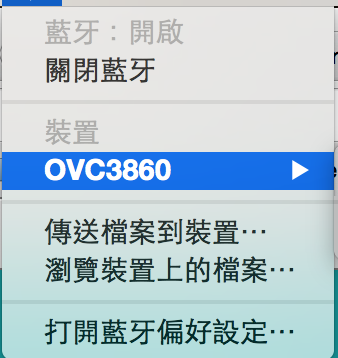
OVC3860是藍芽音訊IC,只要上電源就可以直接用還不用直流阻隔電容,能直推40mW/32ohm不用放大器,也能從UART做操控,由於沒找到這個郵票孔接腳的Eagle Packge所以我畫了一個放在我的github。過去一年囤積太多材料,所以最近做的東西都是些實驗的小模組,到時候可以整到其他地方,最近消耗一些後才會再從淘寶買其他東西來玩玩。


Download:
2015年5月6日 星期三
PCM5102A
兩年前拿到的I2S DAC IC,無奈最近一直很忙上週才找一天時間設計實驗版然後做出來,現在接在喬治查爾斯的系統(PCM2706+真空管buffer+前級放大)聽起來解析度明顯提高,接下來就在把PCM2706畫在一起,真不知道啥時有空,還有我的IV-18鐘要做...
話說手邊有很多模組都找不到Eagle PCB的Packge,所以我建了一些放在Github,目前有PCM5102A,TEA5767,PJ-327A,S3860M-S等等...未來可能會再增加


Download:
github
PCM5102a.zip
話說手邊有很多模組都找不到Eagle PCB的Packge,所以我建了一些放在Github,目前有PCM5102A,TEA5767,PJ-327A,S3860M-S等等...未來可能會再增加


Download:
github
PCM5102a.zip
2015年1月18日 星期日
STM32F10X Nano ver1.0.0


2014年12月28日 星期日
JLINK ARM-OB STM32F103C8T6 (DIP)
說來也蠢,之前就想做STM32的debugger,我慣用的是STLINK + ST-UTIL + ARM-GDB,所以習慣上我還是比較常用discovery上的STLINK/V2,前陣子在網路看到一個叫JLINK的東西以為也可以用ST-Tools,結果直到昨天做了才知道這只能用SEGGER-Tools XDDDDD,還好本來SMD版本要送去淘寶給人洗板不過做了DIP版就發現XD,但是其實也還不錯用拉只是我不習慣而已,將firmware由SWD寫進後用JLINK-Commander可以將firmware升級,要注意的是輸出入的電壓都是3.3v!


Download:
MC34063 DC/DC - IV-18 Power Supply
前陣子想說來完成IV-18 Clock送人(話說三四年前會做IN-16 Clock也是送人),所以先從IV-18的驅動電源開始,IV-18看網路的datasheet要40v才能驅動,不過之前在口丁聽到隨手小記的主人說只要30v便可驅動,因此找了MC34063弄了一個實際測試輸入5v輸出可調整約20v-40v的DC/DC,只要將升壓後的電源接至VFD驅動IC如MAX6921的VBB就可以了。
VCC輸入5v而VSS為輸出,兩個VR可調整。

Download:
訂閱:
文章 (Atom)